

Implementation of cruise control:
My central electronics unit(BCM) 6R0 937 087P supported cruise control, so it is not necessaryto change, ordered the following
1. Steering column switch 1S0 953 503 D (from Skoda Citigo)or 6Q0 953 513 AM 9B9 or 6Q0 953 503 FF — 1pc.
2. Stall bolt WHT005336 — 2 pcs.
3. Small bracket 6Q0907 500 E (could not be required) — 1 pc.
4. Repair wire 000 979 009 (two terminals at the ends) — 1 pc
5. Repair wire 000 979 031 — 1 pc.
Since the repair wire (item 4.5),could be expensive, sometimes cheaper to buyseparate terminals and wires and crimp them on wire length necessary (but stillhave to find where to get them, because in such liitle amounts itis not sold)
a. Terminal N 907 64701 — 10 pcs. (steering column into the socket — 6 pieces, tothe connector BCM — 4 pieces)
b. Terminal N 103 35807 — 1 pc. (to the ECUconnector)
c. Terminal N 907 32603 — 1 pc. (to the fuse box)
d. Wiresection 0.35-0.5 mm2(better to take the 0.35 mm2)
6. The sealing sleeve 357 972 740 E — 1 piece
7. The diode (I'd unsolder from the power supply of anold VHS) — 1 piece
Installationand connection:
1) Remove the battery terminal and wait atleast 10 minutes for the airbag’s capacitors to be discharge. During this time,you can, take off the upper cover of a steering column and unscrew the 3 screwsthe Torx 20 on the lower cover.
2) Remove the airbag and steering wheel.Undertake on both sides of the lower half of the airbag and pull it over. Thelower "locks" of the airbag come out from the sockets in the wheel.Then turn the steering wheel to 90 degrees. Shift from the back side bracket,simultaneously tighten the pillow itself. The same provide on the other side. Thenremove top "locks" of the airbag. Disconnect thecables. In my case, two from the contact ring and multifunction control unit.
Video with the processof removing the airbag is on the cloud.To remove the wheel, unscrew thetwelve-star M12 bolt. Mark the bolt and the steering wheel, then tokeep the same tightening .But I did not do that. And pay attention to the scratches on the shaft andon the steering wheel — then they will have to comply.
But for safety before removing thesteering shaft to put the wheels straight. Once the bolt loosen you mustremove the wheel from the shaft hit the rim of the steering wheel. Then unscrewthe bolt and take off the wheel safely. Video of the process to remove thesteering cloud (I know that in this way to build a too is nonobservance — but that was near hand)
As the wheel removed, better secure therotating part of the slip ring to the body with adhesive tape. Since it is woundtrail and it is targeted at a certain number of turns of the steering wheel ineach direction. Wrong on the back — you can then damage the trail and did noteven feel it. However, some indicators of slip rings are "forwardposition" — as in my case (without the steering angle sensor)
If you slip ring without such indicatorand you accidentally spun the ring and do not know — where the middle? —it is not the problem. Without applying force rotate the ringin one direction until feel resistance, and also to the other side (in my caseit's 4 full turns), and find the middle
3) Remove the bottom column casing .
4) Raise the latch connectors / pads steering column — Connector "driveoff" back. Torx screwdriver 25 Loosen the screw clamp stalk and remove the Lenkstock from the steering column to the end, bringing theconnector out.
5) Remove the connector cover. Insert the crimped wires of scheme in cell connector from 26 to 31.
Wires inserted, but has not instituteduntil it stops
Do not forget to implement in the wirefrom pin T41/31 include diode (I 'd got it from an old VHS from power supply). Thus, the depth of thesteering column will leave 5 wires. Insulate all ofthem and close the connector cover.
In my case the connector also sweep wireto connect the sensor with the steering angle so they do not all fit under thecover of the connector. These are thin wires that I found on the automotivemarket (section 0.5 to 0.75), but it is better to take 0,35mm2.
6) Put the new Lenkstock with tempomat. In my case, yet another slip ring(since the angle sensor). You can mount the wheel andthe airbag .Pay attention to the marks on theshaft and on the steering wheel — they have to comply. If you forgot to markthe bolt tightening torque, in my experience observed, from the moment oftouching the steering hub cap bolt, crank the bolt for a quarter turn.
7) Next on the scheme4 wire go to the central electronicsunit BCM — connector "73B". Detachable connector, remove thecover, enter the crimped wires into the cells 44-47, and collect back all putin place. The fifth wire — "power supply" — you need to pick up tothe fuse box. By wiring SB11,
![]() The wire from 73B/45 goes to themotor compartment.
The wire from 73B/45 goes to themotor compartment.
In my case the color gray-blackdetachable engine ECU. I lead the wire down to the engine ECU.
9) the engine ECU is beingprotected from removing connectors with two brackets and two screws with “breakawayhats”.
10) Move the retainer larger connector(marked in red) in direction — from the drive off and remove it.
Squeezing the cover in the area of theside latches (circled in green) and end hooking screwdriver remove the cover.
On the back of a white stopper move theterminal.
For the CFNA ECU We take out the plugfrom the cell 24 (in blue circle). Terminal N 103 358 07
For the CBZB ECU We take out the plugfrom the cell 45 (in blue circle). Terminal N 907 647 01
(note. If you know the cell and terminal for another engines - please write, I will add it here)
Enter crimped wire with seal in the cell until it locks and put the stopper in place of
terminals.

CFNA
9a4ced2s-480.jpg
CBZB
11) Dress battery terminal
Activation and coding:
1) Connect the cord to the VCDS, turn the ignition
2) Go to the 09 block (on-board electronics — BCM) and activate cruise control: Coding (Coding07) Long Coding (Long Coding), put mark in the 7 bit 17 byte
3) Go to the 01 unit (engine ECU) and activate the cruise control. There are two ways:
a) Coding (07Coding) Long Coding (Long Coding), put a check in bit 5 of 5 bytes (but coding could not be accepted, I have so happened, switch the ignition off / on — the second time - success)
b) Coding II (CodingII) and enter the code 11463. (to turn off the cruise control code 16167)
To make sure that everything is done correctly note the Component field in the main menu of Block 01. There will be an additional letter G (from the GRA).
before
after
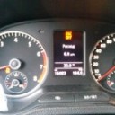
So I'd changed before instrument cluster, I have at the cruise control indicator light
-
 Indicator cruise control